MTL5516C SWITCH/ PROXIMITY DETECTOR INTERFACE
Update: 2016/5/18 View:
- Brand: MTL
- Type: MTL5516C

Introduction
The MTL5516C enables two safe-area loads to be controlled by aswitch or proximity detector located in a hazardous-area. When
selected, open or short circuit conditions in the field wiring are
detected by the line-fault-detect (LFD) facility and also indicated on
the top of the module. Phase reversal for each channel is selected
by a switch on the side of the module and output is provided by
changeover relay contacts.
SPECIFICATION
See also common specificationNumber of channels
Two
Location of switches
Zone 0, IIC, T6 hazardous area
Div. 1, Group A hazardous location
Location of proximity detector
Zone 0, IIC, T4–6 hazardous area if suitably certified
Div. 1, Group A hazardous location
Hazardous-area inputs
Inputs conforming to BS EN60947–5–6:2001 standards for
proximity detectors (NAMUR)
Voltage applied to sensor
7 to 9V dc from 1kΩ ±10%
Input/output characteristics
Normal phase
Outputs closed if input > 2.1mA (< 2kΩ in input circuit)
Outputs open if input < 1.2mA (> 10kΩ in input circuit)
Hysteresis: 200μA (650Ω) nominal
Line fault detection (LFD) (when selected)
User-selectable via switches on the side of the unit. Line faults
are indicated by an LED for each channel. The channel output
relay is de-energised if an input line fault is detected.
Open-circuit alarm on if Iin < 50μA
Open-circuit alarm off if Iin > 250μA
Short-circuit alarm on if Rin < 100Ω
Short-circuit alarm off if Rin > 360Ω
Note: Resistors must be fitted when using the LFD facility with a contact input
500Ω to 1kΩ in series with switch
20kΩ to 25kΩ in parallel with switch
Safe-area output
Two single-pole relays with changeover contacts
Note: reactive loads must be adequately suppressed
Relay characteristics
Response time: 10ms maximum
Contact rating: 250V ac, 2A, cosØ >0.7
40V dc, 2A, resistive load
* Signal plug HAZ1-3 is required for access to this function
LED indicators
Green: power indication
Yellow: two: channel status, on when output is energised
Red: two: LFD indication, on when line fault detected
Maximum current consumption
35mA at 24V
Power dissipation within unit
0.84W at 24V
Safety description (each channel)
Vo=10.5V Io=14mA Po=37mW Um = 253V rms or dc
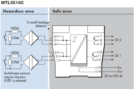
Terminal Function
1 Input –ve (Ch 1)
2 Input +ve (Ch 1)
3 To earth leakage detector*
4 Input –ve (Ch 2)
5 Input +ve (Ch 2)
6 To earth leakage detector*
7 Normally-closed contact (Ch 2)
8 Common (Ch 2)
9 Normally-open contact (Ch 2)
10 Normally-closed contact (Ch 1)
11 Common (Ch 1)
12 Normally-open contact (Ch 1)
13 Supply –ve
14 Supply +ve
More Products